
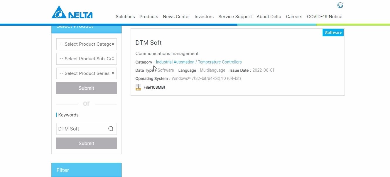
- Download DTM Soft from DELTA download center.
- Open DTM Soft,click New project,give Project name and save.
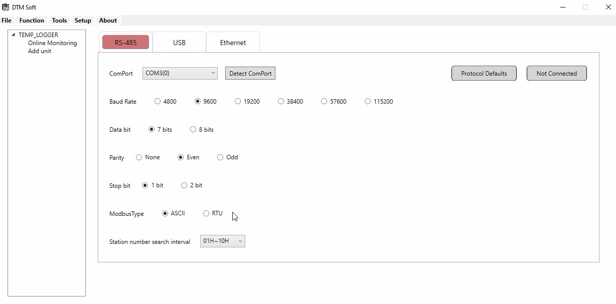
- A new window opens for the DTM Soft,click on RS 485,give com port.
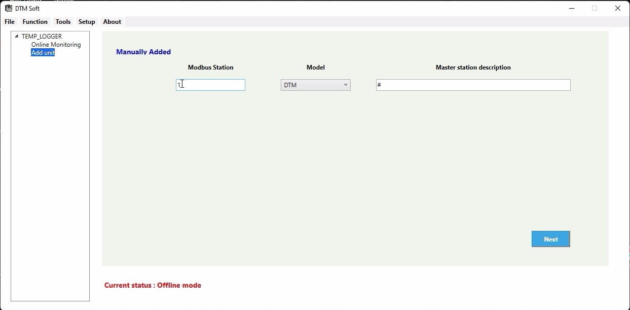
- Click Add unit on the left side,Assign modbus station number and model name,then click next.
- After giving next,a Parameter setting option will be displayed at the left side of the screen.
- Click on the DTM 1-0 below the parameter setting.A window opens give the input type as jPt100(for RTD) in INPUT option.(NOTE:You can select the sensor type that you have.)
- You can change the measuring range of the selected sensor corresponding to your calibration range or you can leave the universal range that is assigned during the selection of the sensor.
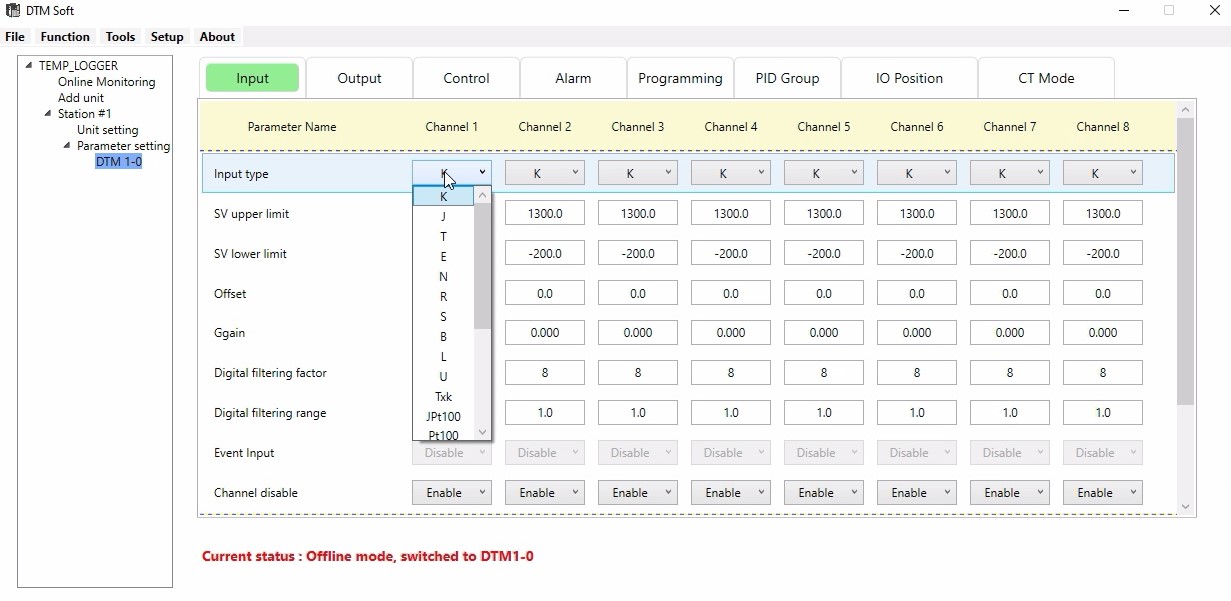
- Since we are using 4 channels,Enable the first 4 channels and Disable for next 4 channels.
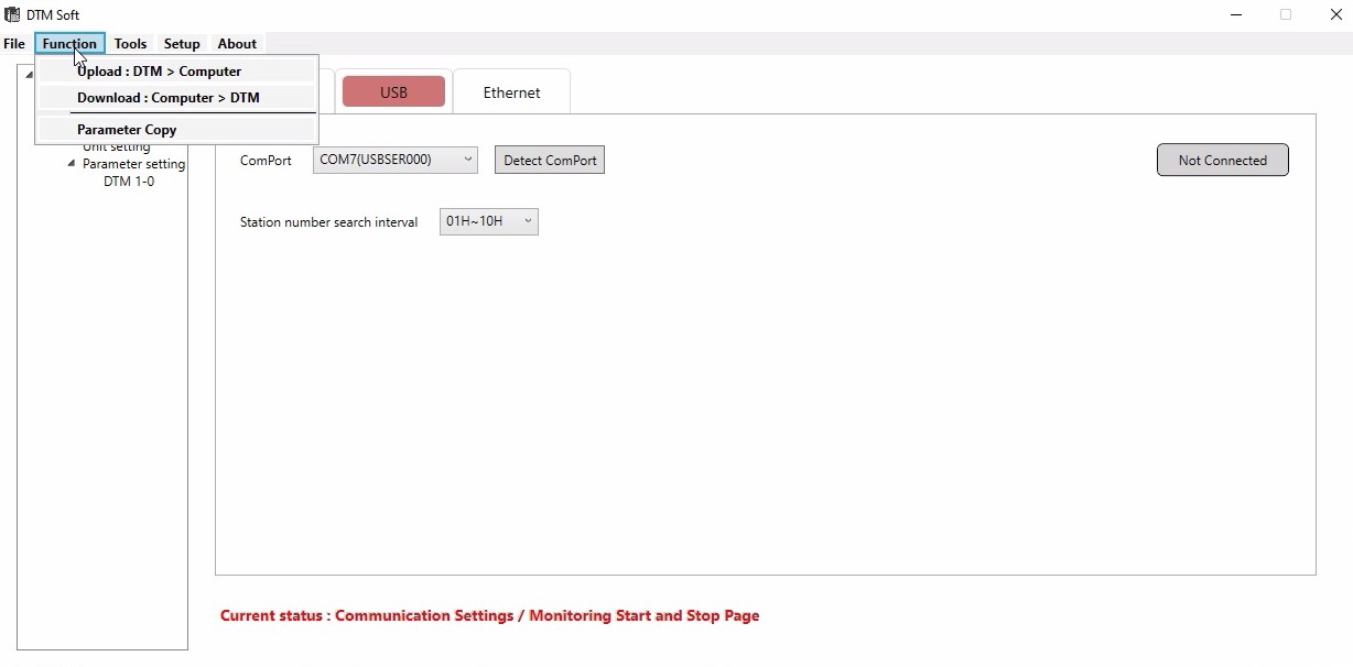
- Then go to USB option at the top, go to Function at the left corner.
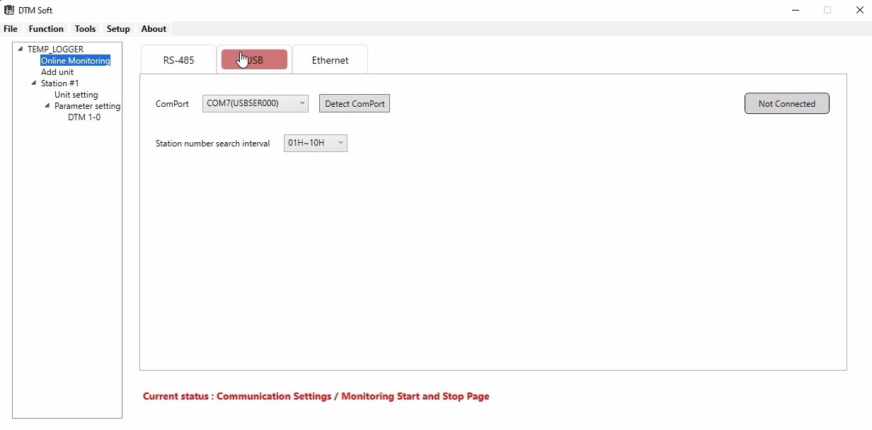
- Drop down and give Download,the scanning will be processed.
- After scanning a window will open click on the option given under Online configuration,then give OK.

- Download will be in progress.After completion give OK.
- Next click on the Not connected option on the right side,it will changeto Connected,Give yes for the popup message,and scanning will be progressing.
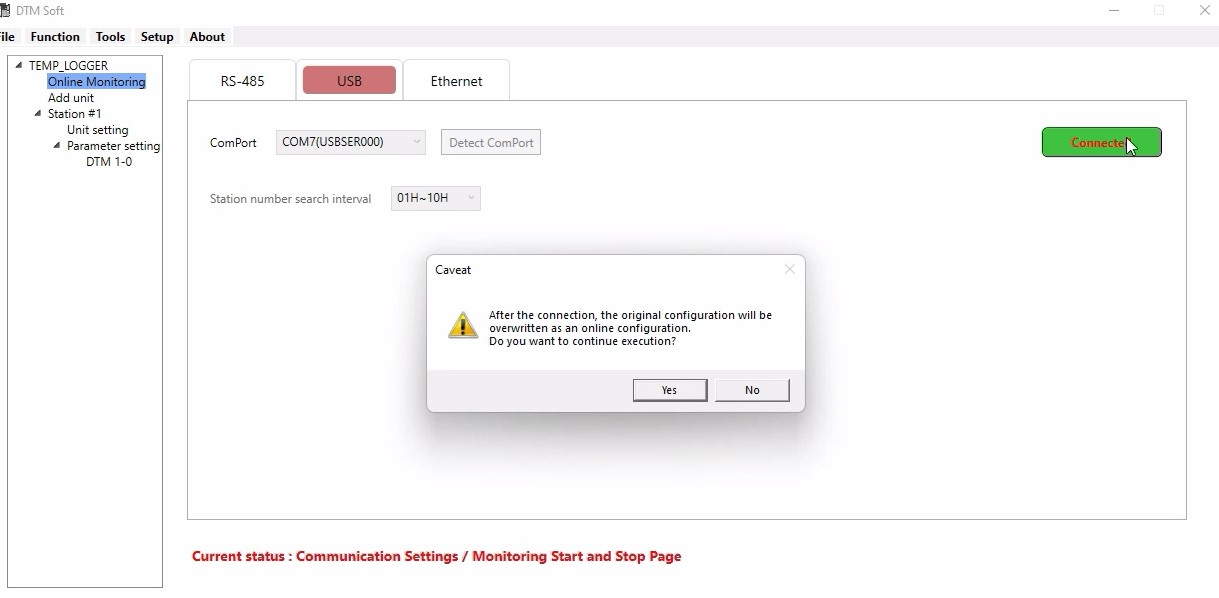
- After the scanning,the communication will be established between the PC and Scanner.
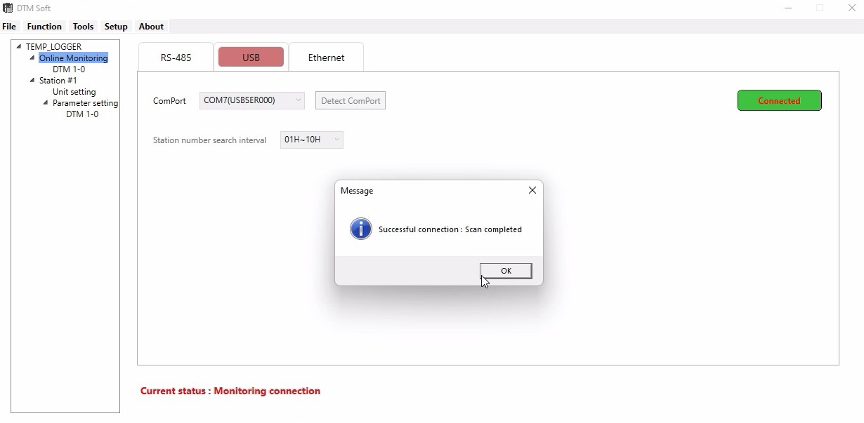
- Go to Online monitoring,click on its sub option DM 1-0,a window opens for that,there we can see the Process value of each channel.
- If the sensor is not connected to the terminals then it will shows that "sensor not connected".


CONFIGURING DELTA ANALOG MODULE (DVP-O6XA-S) WITH DELTA PLC (DVP-12SA2)
1.WIRING DIAGRAM
- NOTE: External 24vdc needs to connect with module
- Check and confirm the module number and whether it will communicate with PLC in manual
PLC Programming:
- Create a new project.
- Select SA2 model PLC
- · Select the Auxiliary Setup for Extension
- Select the place of the AI module from the PLC don’t consider the DI and DO module
- · Select the DVP-06AX-S model AI module and go to setup
- · Click #2Mode setting
- · Select Write register (Generate TO Instruction)
- · Condition as LD M1000 for always On condition
- · Select (-20mA - +20mA) as choice of programmer
- · Click Preview ->Add to List instruction get appears on Instruction List
- Select and configure each channel to read from the analog module
· Click the
- · Click the check box of #CH Input Average -> Read Register (Generate FROM Instruction)
- · Condition as LD M1000 for always On condition
- · Give alternate register number in Register for Storing Data
- · Click ok to add the corresponding API as figured in the below picture
1. Here K0-constant 0 is mentioned in the module position
2. K1 as #1Input mode
3. H6DB as module number
4. K1 Number of Data
- Now I need floating datatype so enabling M1163 bit for floating data type
- Scaling has to be done as per the double data type scaling with floating F constant
- First, all raw values need to convert to float type, and then using DSCLP scaling has to be done as follows
- Here maximum engineering values are mentioned
- Here minimum engineering values are mentioned
- Here max sensor scale value is mentioned
- Here min sensor scale value is mentioned
- Resolution varies based on the modules we have chosen.
*Floats accommodate 32-bit so we are using DMOV D100, D102
What is Core Industry?
Generally, when I’m doing interview with engineers they mostly using this word core industry. “I don’t like software industry; I would like to work in the core industry”.
From that I can understand one thing is, people thinking that jobs segregated in 2 way
1. Software
2. Core
What is core industry in engineers mind commonly???
hardware/manufacturing or civil mechanical electrical electronics etc…
Is it right?
Not exactly.
Then what is core industry?
Core industries can be defined as main or key industries of the economy. In most countries, these particular industries are backbone of all other industries. In India, there are eight core sectors comprising of coal, crude oil, natural gas, petroleum refinery products, fertilizers, steel, cement and electricity. The eight infrastructure sectors constitute 40.27% of the total index of industrial production (IIP)
Reference: ........ currentaffairs.gktoday.in/tags/core-industries © GKToday
Now we can discuss the topic. Industry classified as
1. Manufacturing industry – producing goods – car mobile food cloths TV etc…
2. Service industry – Provide service either directly or indirectly to the manufacturing industry – Software banking customer care etc…
So job also defined in the same way. That is any engineer can get or work in the manufacturing side or service side.
Suppose you are an electrical engineer you can work as a production engineer, maintenance engineer, design engineer, sale engineer or marketing engineer Etc.., in the company.
In the above set of job we are going to apply our knowledge and doing work. Engineers come under skilled. Now a day we are using software in all areas. That means software is not a separate area to do work. It is also a part of service, related to manufacturing.
Manufacturing is the process to produce the product or goods were the service is nothing planning, design, procedure and support (data or document to do manufacturing).
Here after we can’t say software not related to my study, any engineer can be a software engineer. Software is the tool to do work, design, plane, database and forecasting etc...
Auto CAD is the software electrical engineer can design electrical concept like panel and circuit designing.
Mechanical engineer can design the manufacturing plan, structural plan and many.
Software giving plan for the manufacturing industry, SAP ERP etc…
You can ask one question, then what is role of CSE and IT, they develop this all applications Auto CAD, SAP, ERP, MS office, VB, C, C++, Java etc…
One thing I can say, I have to say…
Choosing the job is related to your interest, skill and what you are studied…..
Electrical engineer should be an electrical engineer….
- Connect the 1763-NC01 extension card to the 8 pin RS-485 port of the PLC CPU unit.
- In 1763-NC01 extension card connect A→A(A+) to the destination module or slave controller that’s RS-485 enabled. Likewise B→B(B+).
- Configure the slave device with Slave ID, Data Bits, Baud Rate, Stop Bits and Parity. Better have those with defaults unless and otherwise more than one slave is to be connected with the PLC. By default Baud Rate will be 9600 for most of the devices, Slave ID 1, Data Bits 8, Stop Bits 1 and Parity None.
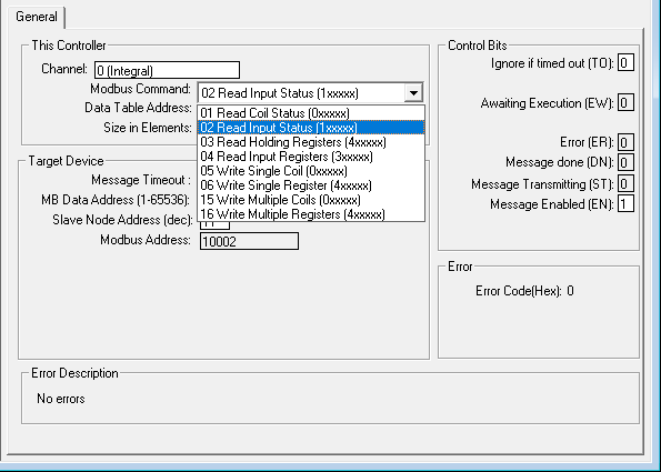
- Note down the data that’s to be read or written on to the slave device and their respective address. Usually Read/Write Coil will be in the address 0xxxx, Read Input Status in the address 1xxxx, Read Input Register in the address 3xxxx, Read/Write Holding register in the address 4xxxx.
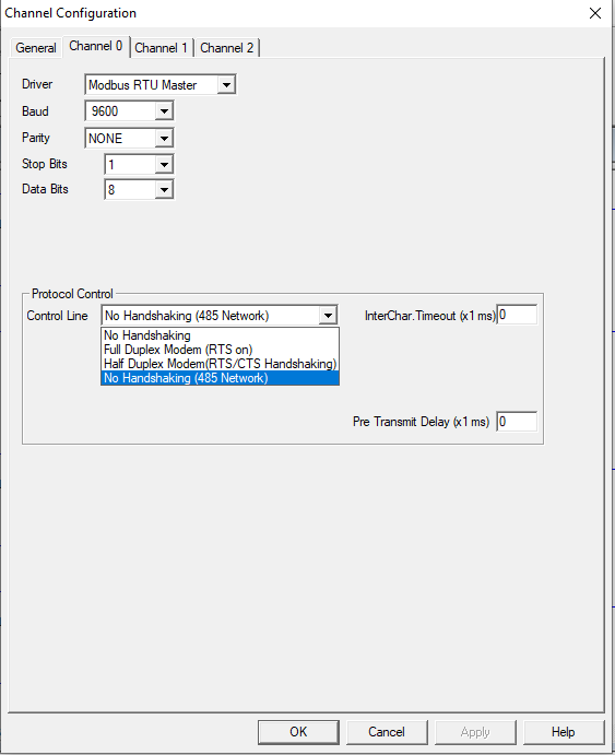
- Open the RsLogix 500 Pro project and Double click on the Channel Configuration. Usually RS-485 will be in Channel 0. Configure Data Bits, Baud Rate, Stop Bits and Parity as per the Slave Device configuration. Make sure the entire slave device that’s to be communicated has the very same configuration.
- Since only A and B terminal is connected, select the option “NO HANDSHAKING (RS-485 NETWORK)” in the control line dropdown list box.

- Insert MSG block and enter a message address in MSG File (For Example ‘MG9:0’)
- Now Double Click on the Setup Screen in MSG Block and configure the data that’s to be read or written.
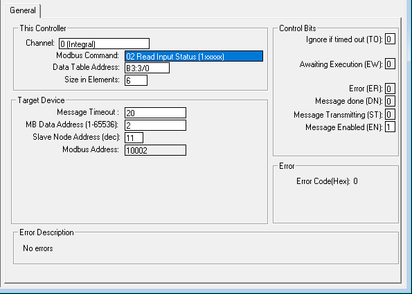
- In Channel, select 0(Integral) (Since RS-485 Communication is in Channel 0). As per S.No. 3 Select in the Modbus Command drop down List.
- In Data Table Address as per the data type enter the address (For Example ‘N7:0’ for integer and ‘B3:0/0’ for Binary). In Size in Elements, enter the number of continuous data that’s to be read or written which reduces the number of MSG block to be used.
- In MB Data Address enter the Slave Data Address (For Example enter 1 for 40001 which will be displayed in Modbus Address).
- In Slave Node Address enter the respective Slave ID.
- Make sure that each slave devices has a unique slave id.
NOTE: MSG Block is activated at every rising edge of the pulse or continuous signal. Hence a pulse signal is mandatory even when only a single MSG Block is used or a timer with a comparator before a message block can be considered an option for multiple MSG Blocks. This is because only one slave should be active at a time.

Welcome to Math Technologies Blog
Our Aim is “To connect the Industry – Industry – Engineer”
Why?
We are a company who is doing/providing Automation solution to the industry. That means we as a company doing projects for the industry to automate the process/machines.
What is Industry?
Manufacturing place or service providing place.
In that case we are also an industry because we are providing service to the manufacturing industry.
Why we want to connect the engineer & industry?
Because Industry own by money but run by an engineer!
Industry is a business model which aim is making money by providing Product/Service to the customers. It is done by people & Material resources.
From where we can get the people?
From where we can get material resources?
Both are important for any industry/company to do business.
We are industry we are working for an industry and the both industry need people/engineer as well material resources.
Here the place to connect Industry-Industry-Engineer
- SoMachine To Citect Studio:
- Create the PLC Tags in SoMachine as Global Variables(GVL).
- Create Symbol Configuration and click the Check box in GVL to access.
- Open OPC Server.
- Right Click Server –>Append PLC –>Click Connection –>Edit.
- Enter the PLC Name as per the SoMachine Software.
- Check the PLC Name in SoMachine –>Tools –>OPC –>CoDeSys PLC Address.
- Then save OPC Configuration.

In Citect Studio:
- Open Citect Studio –>Topology –>I/O Devices –>New Device .
- Device Communication Wizard Popup Will display –>Create I/O Server –>Next
–>Create a new I/O Device–>Next –>Slecet the type of I/O Device –>Next –>Select OPC Fountation –>OPC DA Client –>OPC–>Next–>Enter the address(CoDeSys.OPC.DA)–>Next–>Click the Checkbox in the Link I/O Device to an external tag database–>Database type–>Select OPC–>External Tag Database–>OPC Data Access Server Parameter Popup Will Display–>Select CoDeSys.OPC.DA–>PLC(This is the PLC name Created in OPC server)–>OK–>Next–>Finish.
- Now the PLC Tags will connect with SCADA
- Cilck Refresh Tags for further tags added in SoMachine Software.
