- Connect the 1763-NC01 extension card to the 8 pin RS-485 port of the PLC CPU unit.
- In 1763-NC01 extension card connect A→A(A+) to the destination module or slave controller that’s RS-485 enabled. Likewise B→B(B+).
- Configure the slave device with Slave ID, Data Bits, Baud Rate, Stop Bits and Parity. Better have those with defaults unless and otherwise more than one slave is to be connected with the PLC. By default Baud Rate will be 9600 for most of the devices, Slave ID 1, Data Bits 8, Stop Bits 1 and Parity None.

- Note down the data that’s to be read or written on to the slave device and their respective address. Usually Read/Write Coil will be in the address 0xxxx, Read Input Status in the address 1xxxx, Read Input Register in the address 3xxxx, Read/Write Holding register in the address 4xxxx.

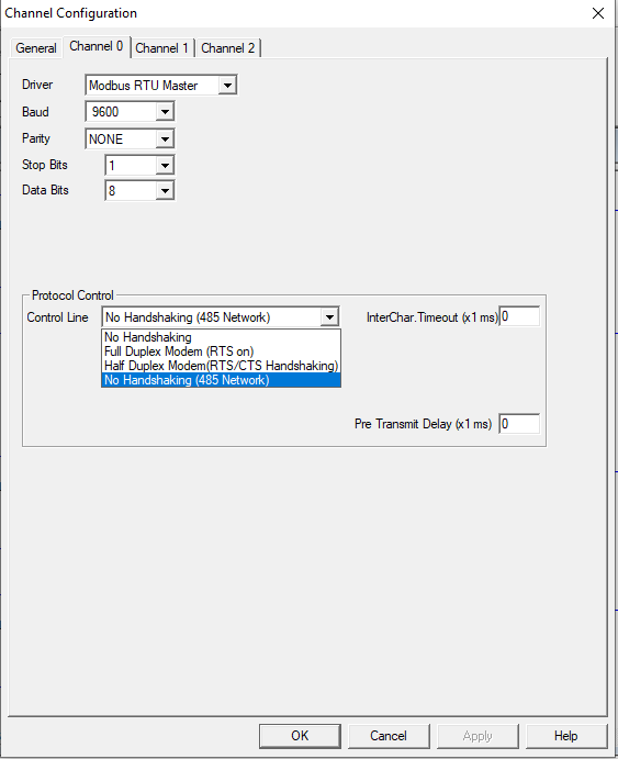
- Open the RsLogix 500 Pro project and Double click on the Channel Configuration. Usually RS-485 will be in Channel 0. Configure Data Bits, Baud Rate, Stop Bits and Parity as per the Slave Device configuration. Make sure the entire slave device that’s to be communicated has the very same configuration.
- Since only A and B terminal is connected, select the option “NO HANDSHAKING (RS-485 NETWORK)” in the control line dropdown list box.

- Insert MSG block and enter a message address in MSG File (For Example ‘MG9:0’)
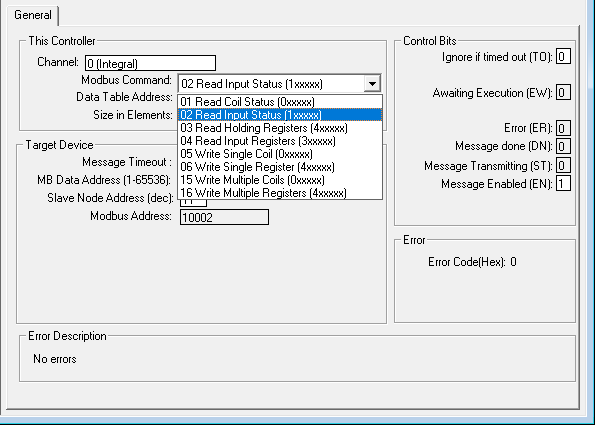
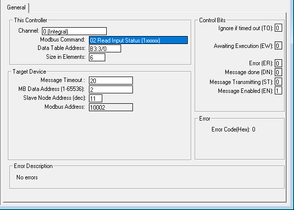
- Now Double Click on the Setup Screen in MSG Block and configure the data that’s to be read or written.

- In Channel, select 0(Integral) (Since RS-485 Communication is in Channel 0). As per S.No. 3 Select in the Modbus Command drop down List.
- In Data Table Address as per the data type enter the address (For Example ‘N7:0’ for integer and ‘B3:0/0’ for Binary). In Size in Elements, enter the number of continuous data that’s to be read or written which reduces the number of MSG block to be used.
- In MB Data Address enter the Slave Data Address (For Example enter 1 for 40001 which will be displayed in Modbus Address).
- In Slave Node Address enter the respective Slave ID.
- Make sure that each slave devices has a unique slave id.
NOTE: MSG Block is activated at every rising edge of the pulse or continuous signal. Hence a pulse signal is mandatory even when only a single MSG Block is used or a timer with a comparator before a message block can be considered an option for multiple MSG Blocks. This is because only one slave should be active at a time.


2 Comments
Nirmal Kumar B says 28-06-2022 15:29
Amazing blog, really usefull for my studies
Nirmal says 28-06-2022 15:50
Test Comment
Leave a reply