

CONFIGURING DELTA ANALOG MODULE (DVP-O6XA-S) WITH DELTA PLC (DVP-12SA2)
1. WIRING DIAGRAM
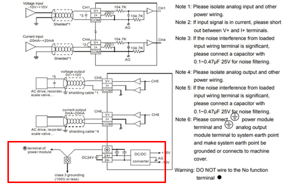
- NOTE: External 24vdc needs to connect with module
- Check and confirm the module number and whether it will communicate with PLC in manual
PLC Programming:
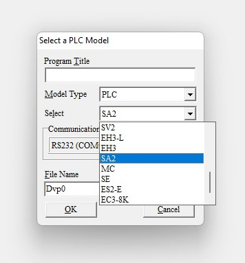
- Create a new project.
- Select SA2 model PLC
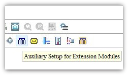
- Select the Auxiliary Setup for Extension
- Select the place of the AI module from the PLC don’t consider the DI and DO module
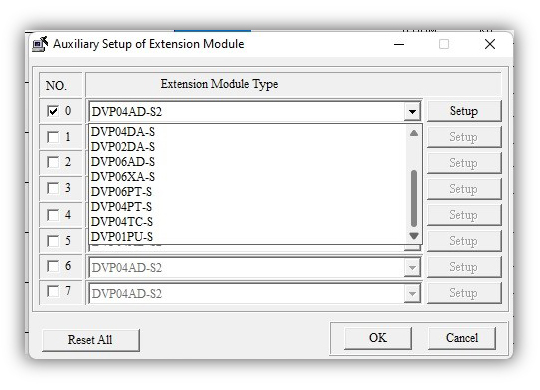
- Select the DVP-06AX-S model AI module and go to setup
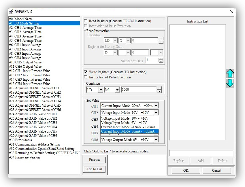
- Click #2Mode setting
- Select Write register (Generate TO Instruction)
- Condition as LD M1000 for always On condition
- Select (-20mA – +20mA) as choice of programmer
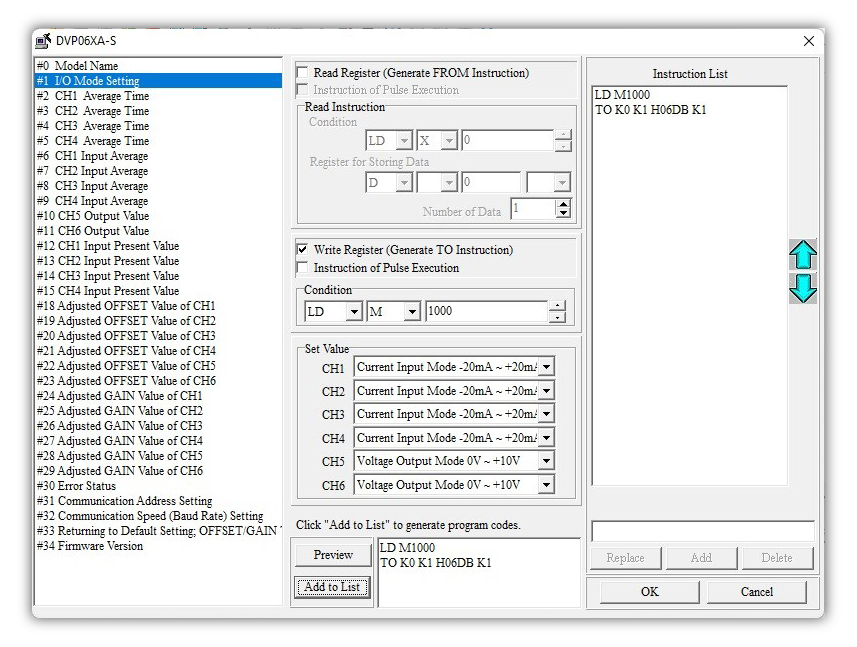
- Click Preview ->Add to List instruction get appears on Instruction List
- Select and configure each channel to read from the analog module
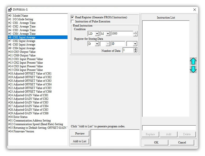
- Click the check box of #CH Input Average -> Read Register (Generate FROM Instruction)
- Condition as LD M1000 for always on condition
- Give alternate register number in Register for Storing Data
- Click ok to add the corresponding API as figured in the below picture
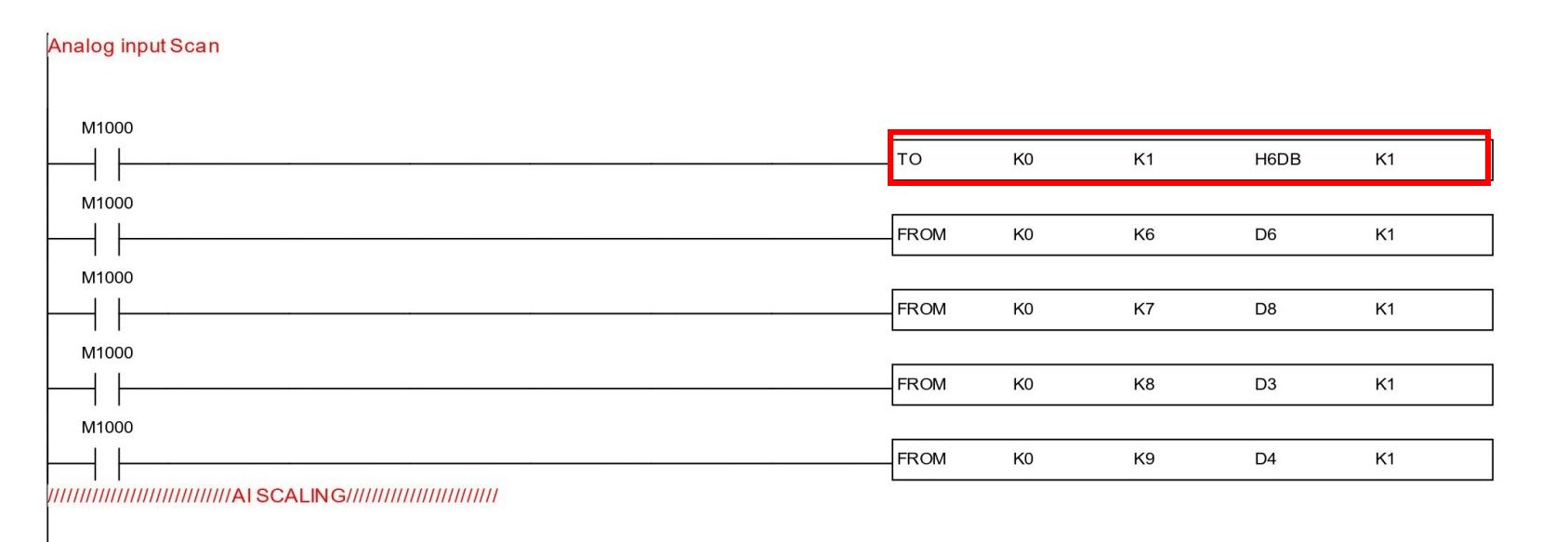
- Here K0-constant 0 is mentioned in the module position
- K1 as #1Input mode
- H6DB as module number
- K1 Number of Data
- Now I need floating datatype so enabling M1163 bit for floating data type
- Scaling has to be done as per the double data type scaling with floating F constant
- First, all raw values need to convert to float type, and then using DSCLP scaling has to be done as follows
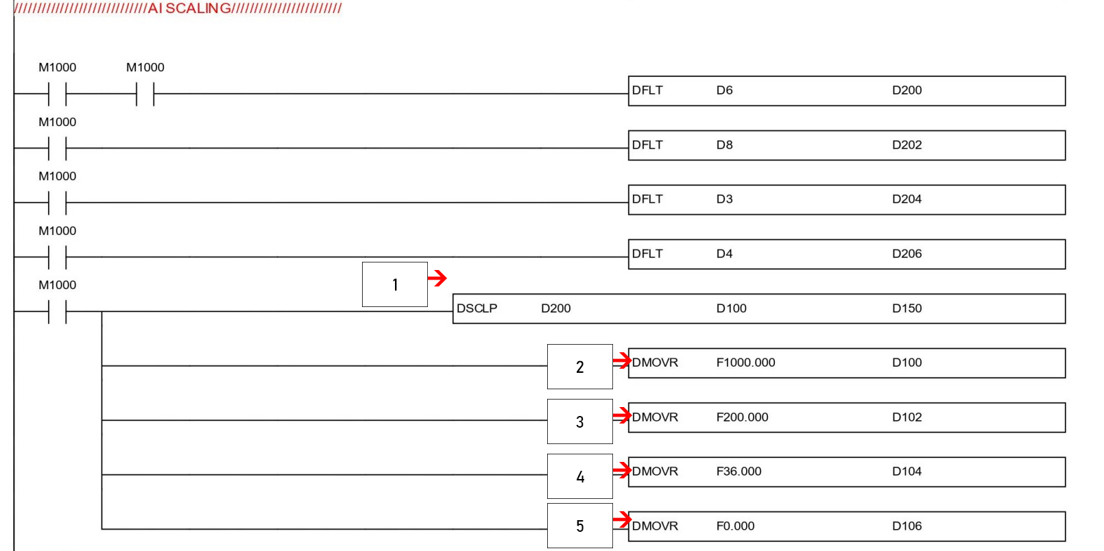
- Here maximum engineering values are mentioned
- Here minimum engineering values are mentioned
- Here max sensor scale value is mentioned
- Here min sensor scale value is mentioned
- Resolution varies based on the modules we have chosen.
*Floats accommodate 32-bit, so we are using DMOV D100, D102